Infrared Emitters
The emitters are a garden variety
type and readily available from several sources. The parts list on the schematics
page provides parts number for Mouser
Electronics but they are available from other vendors. If you decide
to use another emitter or use a different supply voltage you will have to
recalculate the value of its series resistor. Here are some links with
online calculators:
Calculator
1
Calculator
2
Calculator
3
Calculator
4
The emitters should be mounted in a way to make them
easier to "aim" at the detectors. You will have to design your own that is
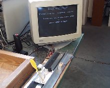
suitable to your application. In my example I am using it with a maglev
track purchased from Kelvin and
mounted both the emitters and detectors in small blocks of wood. You can
see a drawing on the schematics
and drawing page. You can also see pictures on the pictures
page.
Voltage for the emitters, 5 volts DC, is supplied from
the computer. I "tapped" into an extra cable from the computer's power
supply. These connectors have two black wires, one red wire, and one
yellow wire. The black wires are ground (negative). The red wire is 5
volts (positive). The yellow wire is 12 volts (positive).
Infrared Detectors
The
detectors are mounted in a wooden block like the ones used for the
emitters. Again, see the drawings
provided. I show that the emitter is inserted into the hole and
"backfilled" with hot glue. The glue is transluscent and will allow light
to enter through the back of the block. If this is a problem just cover it
with a piece of black electrical tape.
The only item that I have
not added is an infrared filter for the detectors. In my application I did
not find that I needed one, but I have read that ambient light might
sometimes create a problem preventing the detectors from responding to the
emitters. You can get an infrared filter and place it over the detector
opening to allow only infrared to enter if you experience this problem.
You could "liberate" the filter from a dead VCR or other device controlled
by an infrared remote.
The Interface Circuit
Board
The interface circuit sits between the
emitters/detectors and the computer. In this design it supplies voltage to
the emitters and monitors the resitance across the detectors. Complete
schematics for the board are on the schematics
and drawing page.
When infrared light strikes the detector the
resistence across it changes. By connecting it to the base of the NPN
transitor we use it to control the current flowing through the
transistor's Collector-Emitter path, creating a sort of switch that is
toggled by the presence if the infrared beam.
The red LED on the
circuit board provides visual feedback so you will know when the beam is
interupted. The LED will be on when the bean is detected and it will dim
when the beam is blocked.
The
Computer
I have tested this using a 486-33 computer that is
running Windows for Workgroups. You do not need Windows as this is a
DOS-based program that we will be using. I have run similar programs on a
386 and see no reason why it would not run equally as well on a 286. That
said, the computer also needs a functioning parallel port. This is where
you plug in the printer. I say "functioning" because, since the advent of
Windows 95, not all parallel ports behave the same. Usually, and I stress
"usually," they do, but on some machine Windows wants to control the port
or the port's address are not standard. For these reasons, I really prefer
to use an older computer, not to mention that these computers are
otherwise destined for the junkyard.
Before we go and talk about
software, lets look a little more at why the parallel port is so
important. The port is a DB-25 modular connector. It has 25 pins or holes
depending on whether you are looking at the plug or the socket. If you
look at the plug-type (male), it will look like the diagram below:
The pins are numbered and each
is assigned to a specific function. The table below details this:
| Pin Number |
Function |
| 1 |
-Strobe |
| 2 |
Data 0 |
| 3 |
Data 1 |
| 4 |
Data 2 |
| 5 |
Data 3 |
| 6 |
Data
4 | | |
| Pin Number |
Function |
| 7 |
Data 5 |
| 8 |
Data 6 |
| 9 |
Data 7 |
| 10 |
-Ack |
| 11 |
+Busy |
| 12 |
Paper
End | | |
| Pin Number |
Function |
| 13 |
+Selectln |
| 14 |
-AutoFd |
| 15 |
-Error |
| 16 |
-Init |
| 17 |
-Select |
| 18-25 |
Ground | | |
In
some projects, pins 2 through 9 are of interest because they are the
output lines and can be used to control external devices, like robots,
lights, etc. The input lines are of interest to us on this project. There
are 5 of these but we will only be using 2, pins 13 and 14.
These
input lines are an ON/OFF type, that is, if a switch is connected between
one on these pins and a ground connection (pin 18), the computer can
determine if the switch is On or Off.
The Software
This brings us to a discussion of the
software. You can accomplish this with most any programming language but
for this project I selected QuickBasic because it came with Microsoft DOS,
Windows 3.1, and Windows 95 & 98. For a time it could also be
purchased from Microsoft in a full version which included a compiler,
meaning that programs written in this version could be run on computers
that did not have QuickBasic installed on them.
If you want a copy
of QuickBasic, along with other old DOS tools, you can download it by clicking here.
Download it into a new folder. After it arrives, go to that folder and
double-click on the "olddos.exe" file and it will extract the new files
into that folder. QuickBasic is the one name "qbasic.exe." This is an
early version of QuickBasic but will run the sample program provided on
this page. QuickBasic is also on Windows 95, and some Windows 98, CDs
under the name "olddos."
Once we have QuickBasic running, we need
to know the address of the input lines on your parallel port. An address
of "889" is standard but could be different on your computer. The program
below will report the address for us. Type it in to QuickBasic and run
it.
Once you launch the version of
QuickBasic from the Microsoft site, you will get a "Parameters" box.
Just click on "OK." The QuickBasic program will launch and a
"Welcome" screen will appear. Press "Esc" to clear that screen. If
you are running QuickBasic on the same machine that you are viewing
this web page on, you can copy the program below and paste it into
QuickBasic by doing this:
- Select the text of the program by highlighting with the cursor
- Select Copy from the Edit menu
- Launch QuickBasic and clear the Welcome screen
- Hold down the Alt key and press the Enter key to make
QuickBasic run in a Window
- Pull down the Icon in the upper-left corner of the Window to
see its menu
- Select Edit and then select Paste
The program will be
pasted in to the QuickBasic program. Press Alt-Enter again to make
QuickBasic run full
screen.
|
DEF SEG = 0
FOR i% = 1 TO
3
lpt% = PEEK(&H408 + (i% - 1) * 2) + PEEK(&H408 + (i% -
1) * 2 + 1) * 256
PRINT "LPT"; HEX$(i%);
IF lpt% = 0 THEN
PRINT " not found" ELSE PRINT " found at "; lpt%
NEXT
i%
END
|
After you
run the program, you will be shown the status of the 3 possible parallel
ports in your computer. They are named LPT1, LPT2, and LPT3. The program
should indicate that LPT1 is found at 888. 888 is the address of the
output line for that parallel port. Add one to the number to get the
address of the input lines, in this case they would be at 889.
Now
we are ready to use QuickBasic to sniff out information from the parallel
port. The following program will print out a value by looking at the input
line port address:
DO
LOCATE 10,1
PRINT
INP(889)
LOOP
|
The
number that appear on the screen will be the base value of the port when
nothing is connected to it. If you connect a wire between pin 18 and pin
13, the number on the screen will change. Move the wire from pin 13 to pin
14 and you will get a different number. This is how the computer can tell
which switch is pressed.
Now, on to the program that works with
our Elapse Timer. I am not going to place the program listing on this
page, rather I will provide a link to its source code which can be pasted
into QuickBasic. I will also have a link to a compile version that will
run on your computer even if you do not have QuickBasic
installed.
When you start the program it will ask for your port
number. This is the port address for the input lines, so if you used the
above program to determine your address, be sure to add one to it. Next,
it will ask you to calibrate it to your emitters and detectors. Then it
will first read the room light, then ask you to cover the starting-end
beam and then the finish-end beam. That's it. It's ready to time your
runs.
|