How To Build the Device for Unlocking a Combination Lock
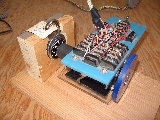


Project Overview
In this project you can build a device that will unlock a combination lock using a stepper motor.

In the pictures I feature you will see that I am using my Version 2 robot. I did this because I already had it working and it saved me the trouble of building a new setup. You can accomplish the same thing just using a single stepper motor and other parts that are listed on the schematic.

The axle on the stepper motor (where the wheel would go on the robot) is connected to the combination lock which is held in a wooden stand. The connection in my example is made with a piece of automotive heater hose which is hot glued to the axle and press fitted to the lock.

The stepper motor is connected to a controller chip which in turn is connected to the computer via the parallel port. The circuit is also connected to a 12 volt power supply on the computer.

The software is written in QuickBasic and is running on a 486 computer running DOS 6. The software asks the user to end the combination of the lock and what number the lock is currently set at. The software then sends pulses to the stepper motor to turn the dial the required revolutions to unlock it.


Project Details
The Stepper Motor

The stepper motor is a standard item retreived from a 5 1/4" disk drive. I provide detailed information
here.

The Interface Circuit

The interface circuit sits between the motor and the computer. It takes the output signals from the parallel port and uses them to switch the correct coils on and off on the stepper motor. I explain these in great deal on my elapsed timer site. You should also look at the schematics and parts list located here.

The Software

Getting QuickBasic Running

This brings us to a discussion of the software. You can accomplish this with most any programming language but for this project I selected QuickBasic because it came with Microsoft DOS, Windows 3.1, and Windows 95 & 98. For a time it could also be purchased from Microsoft in a full version which included a compiler, meaning that programs written in this version could be run on computers that did not have QuickBasic installed on them.

If you want a copy of QuickBasic, along with other old DOS tools, you can download it
here. Download it into a new folder. After it arrives, go to that folder and double-click on the "olddos.exe" file and it will extract the new files into that folder. QuickBasic is the one name "qbasic.exe." This is an early version of QuickBasic but will run the sample program provided on this page. QuickBasic is also on Windows 95, and some Windows 98, CDs under the name "olddos."

This software will probably not work under Windows XP. This is because of the way that XP commandeers the parallel port.

Figuring Out Which Port to Use

Once we have QuickBasic running, we need to know the address of the input lines on your parallel port. An address of "889" is standard but could be different on your computer. The program below will report the address for us. Type it in to QuickBasic and run it.

Once you launch the version of QuickBasic from the Microsoft site, you will get a "Parameters" box. Just click on "OK." The QuickBasic program will launch and a "Welcome" screen will appear. Press "Esc" to clear that screen. If you are running QuickBasic on the same machine that you are viewing this web page on, you can copy the program below and paste it into QuickBasic by doing this:

  • Select the text of the program by highlighting with the cursor
  • Select Copy from the Edit menu
  • Launch QuickBasic and clear the Welcome screen
  • Hold down the Alt key and press the Enter key to make QuickBasic run in a Window
  • Pull down the Icon in the upper-left corner of the Window to see its menu
  • Select Edit and then select Paste
The program will be pasted in to the QuickBasic program. Press Alt-Enter again to make QuickBasic run full screen.


DEF SEG = 0
FOR i% = 1 TO 3
lpt% = PEEK(&H408 + (i% - 1) * 2) + PEEK(&H408 + (i% - 1) * 2 + 1) * 256
PRINT "LPT"; HEX$(i%);
IF lpt% = 0 THEN PRINT " not found" ELSE PRINT " found at "; lpt%
NEXT i%
END


After you run the program, you will be shown the status of the 3 possible parallel ports in your computer. They are named LPT1, LPT2, and LPT3. The program should indicate that LPT1 is found at 888. 888 is the address of the output line for that parallel port. Add one to the number to get the address of the input lines, in this case they would be at 889.

Now we are ready to use QuickBasic to sniff out information from the parallel port. The following program will print out a value by looking at the input line port address:

DO
LOCATE 10,1
PRINT INP(889)
LOOP


The number that appear on the screen will be the base value of the port when nothing is connected to it. If you connect a wire between pin 18 and pin 13, the number on the screen will change. Move the wire from pin 13 to pin 14 and you will get a different number. This is how the computer can tell which switch is pressed.

The Unlock Program

Now, on to the program that works with our stepper motor. The program is available on the software page. Open the one provided in plain text format. It is annotated, explain how each section works.

Basically, it sends pulses to the stepper motor using a process called "interleaving."


This page and its contents Copyright © 2006, Vince Long


Go Back to the Main Elapse Timer Page