|
Step-By-Step Making the Stepper Motor Turn |
 |
|
Step 1 - Retrieve the stepper motor from an old 5-1/4 inch disk drive
|
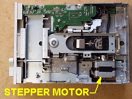 Locate and remove the stepper motor from the drive. There are a variety of motors used in various drives. Ideally we will find a uni-polar motor with 5 leads. Remove any extra hardware from the motor so all that is left is the circular lug on the shaft and the 5 wires. Remove about 1/2-inch of insulation form each wire and tin them with a soldering iron. Locate and remove the stepper motor from the drive. There are a variety of motors used in various drives. Ideally we will find a uni-polar motor with 5 leads. Remove any extra hardware from the motor so all that is left is the circular lug on the shaft and the 5 wires. Remove about 1/2-inch of insulation form each wire and tin them with a soldering iron.
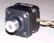 This is a standard stepper motor. This is a standard stepper motor.
|
||||||||||||||||||
|
Step 2 - Retrieve Controller Chip
|
 Locate and remove the ULN 2003 controller chip from the disk drive's circuit board. Use a soldering iron on the chip-side of the board and a "solder sucker" tool on the backside of the board. Locate and remove the ULN 2003 controller chip from the disk drive's circuit board. Use a soldering iron on the chip-side of the board and a "solder sucker" tool on the backside of the board.Some drives do not have that chip. In that case, or if you don't want to desolder the chip, you can buy the chips from Mouser Electronics. They are very inexpensive, that is, less than 50 cents each. |
||||||||||||||||||
|
Step 3 - Build the Parallel Cable
|
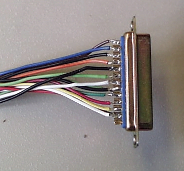 You need to build a cable that has a DB25 male connector at one end and bare wires at the other end. Minimally you need wires on pins 2 through 5 and pin 18. I have some information about the parallel port and the pin outs that you can read here. It will open in a new browser window.
If you'd rather not build a cable, you can cannabalize an old printer cable. Just cut the Centronics connector off the end that normally goes to the printer, remove the insulation, and use a continuity tester to determine which wire goes to which pin at the other end of the cable. |
||||||||||||||||||
|
Step 4 - Set Up the Prototype Board
|
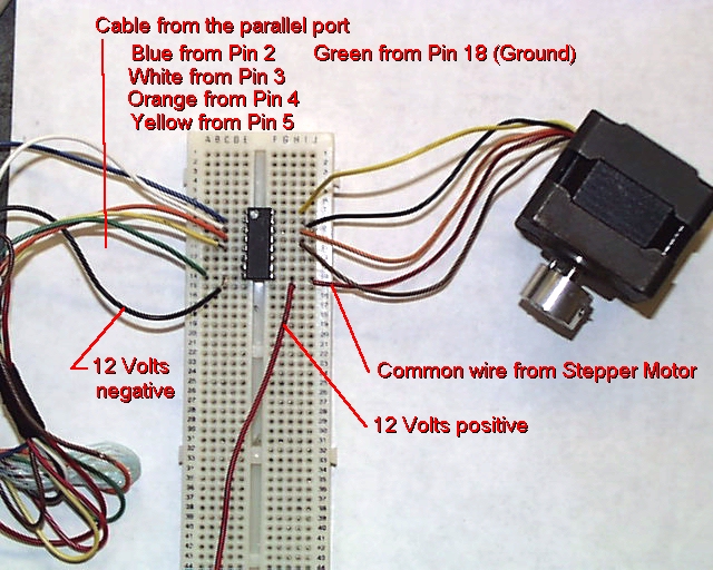 Use a solderless prototype board to make your connections. Plug the chip into the board as shown in the photo and on the schematic. You can click on the photo to the left to enlarge it.
I usually tap into the computer's own power supply for the required 12 volts positive that goes both to pin 9 on the chip and the red wire on the stepper motor. Find an extra connector on the power supply (the ones that go to hard drives or CD-ROMs) and check the voltage with a meter. Two of the wires are grounds and the other two are 5 and 12 volts positive. Here are the pin outs for the standard connector.
The schematic shows a zener diode between the motor and the chip. It is recommended to use one to prevent the back EMF from the motor from blowing the chip, however, I've gotten away without using one. |
||||||||||||||||||
|
Step 5 - Testing
|
Now you are ready to make the motor rotate. First, you should read what I have to say about computers and software for this project on my Ellapse Timer page. I cover the type of computer you can use, type of operating systems supported, how to determine your parallel port address, and so on. Just read the part about computers and programming, then come back here. You can open that section in a new browser window by clicking here. Welcome back. OK, now that we are straight on that, lets try this thing out. I am making the following assumptions:
You can type in the following program or download it. Downloads are in three formats: QBasic Source Code (QBasic required) Text File
When you run the program it will ask you for a "delay" value. The program will use this number to slow itself down, something that is required to allow the stepper motor to function properly. The value that you give depends on the speed of your computer and you have to experiment a bit to find what value gives you the smoothest rotational speed. On a 486 computer try using a value of 30. On a Pentium 230 I use 1,200. The speed of rotation can be controlled, somewhat, by fine tuning the delay, or by changing the pulse sequences. |

www.codecooker.com
Copyright © 2007, Vince Long